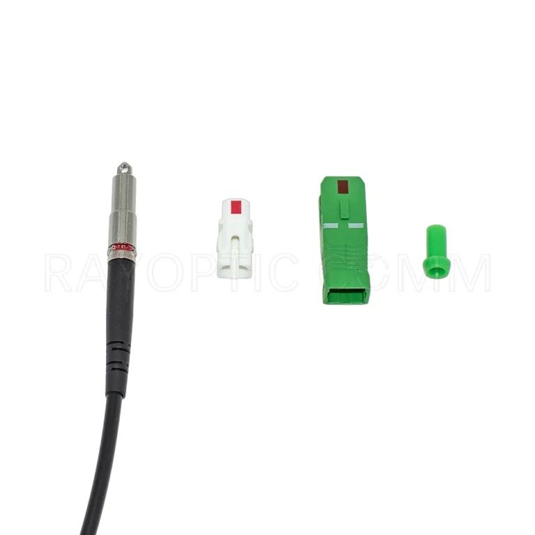
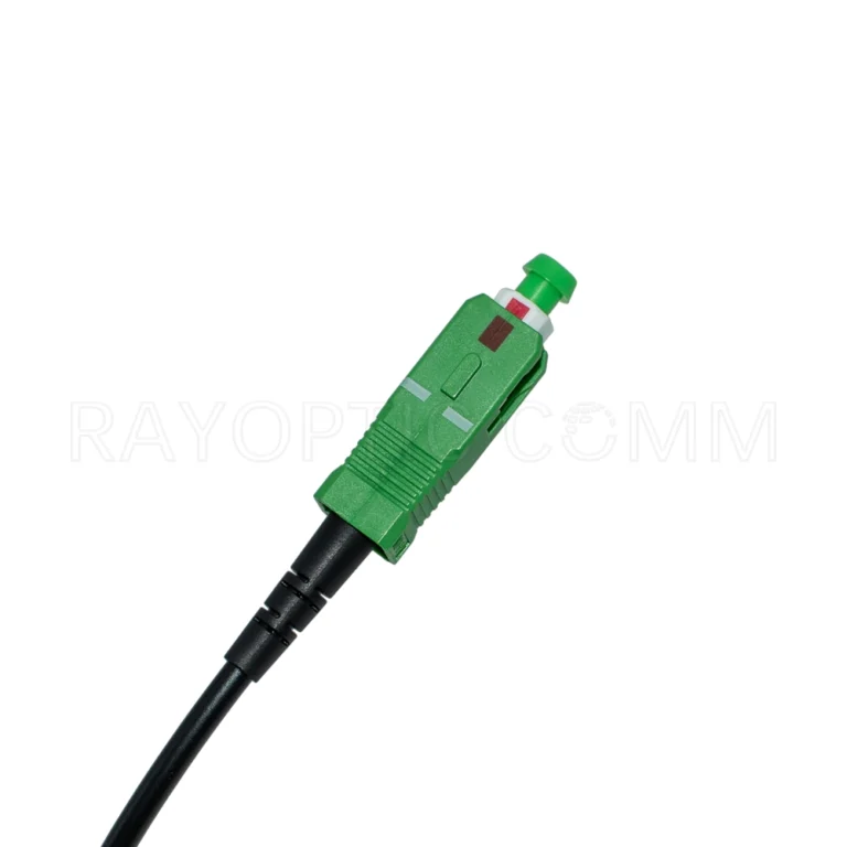
Pullable Pushable Bullet SC/APC to SC/APC Armored Fiber Patch Cord 3mm, G.657.A1, LSZH
Product Overview
The Rayoptic Bullet SC/APC to SC/APC armored fiber patch cord combines factory-terminated optical connectivity with a detachable connector housing for easier cable routing.
During installation, the SC housing remains uninstalled, and a compact metal bullet head protects the connector end. This configuration allows the assembly to be pulled or pushed through suitable wall openings and conduits. Once routing is complete, the installer removes the bullet head and assembles the SC/APC housing.
The bullet head has a maximum outside diameter of 5.9mm and a length of 51.3mm. The cable features stainless steel armor, a 3mm LSZH outer jacket and one G.657.A1 single-mode fiber, making it suitable for FTTH subscriber connections and premises fiber cabling.

Features
Pullable and pushable: Supports pulling and pushing through suitable pathways with the bullet head fitted.
Compact installation end: Maximum Ø5.9mm, with a combined head and boot length of 51.3mm.
Flexible boot: A 10.2mm slotted section can bend during routing.
Detachable SC housing: Assembled after routing to keep the installation end compact.
Factory-terminated connectivity: No field splicing or polishing required during housing assembly.
Stainless steel armor: Provides additional mechanical protection for the fiber.
3mm LSZH cable: Low Smoke Zero Halogen outer jacket.
G.657.A1 single-mode fiber: Suitable for FTTH and premises connectivity.
200N maximum installation pulling force: Supports controlled cable pulling.
Optical performance: Insertion loss <0.3dB and return loss >60dB.
Length options: Available from 5m to 200m in 5m increments.

Technical Specification
| Parameter | Specification |
| Product type | Pre-terminated armored fiber patch cord |
| Connector configuration | Bullet SC/APC to SC/APC |
| Installation-end design | Metal bullet head with detachable SC housing |
| Installation capability | Pullable and pushable |
| Bullet head maximum outside diameter | 5.9mm / 0.232 in |
| Bullet head length | 51.3mm / 2.019 in |
| Fiber count | 1 fiber / simplex |
| Fiber type | G.657.A1 single-mode |
| Cable outside diameter | 3.0mm |
| Cable construction | Armored round cable |
| Armor material | Stainless steel |
| Outer jacket | LSZH — Low Smoke Zero Halogen |
| Connector polish | APC |
| Insertion loss | <0.3dB |
| Return loss | >60dB |
| Maximum installation pulling force | 200N / approximately 45lbf |
| Operating temperature | −40°C to +70°C / −40°F to +158°F |
| Available lengths | 5–200m, in 5m increments |
| Fiber termination | Factory terminated |
| On-site assembly | SC housing assembly after routing |
Installation Overview
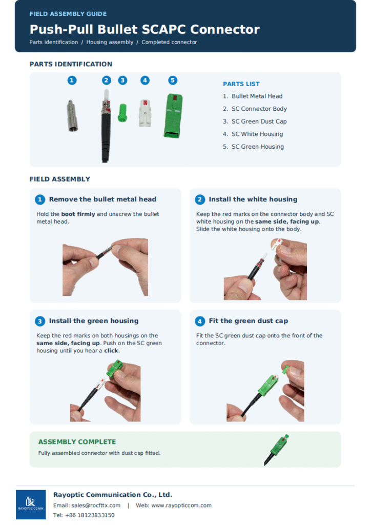
Unscrew the bullet metal head. Hold the boot firmly while removing the metal head.
Install the SC white housing. Keep the red marks on the connector body and white housing on the same side, facing upward.
Install the SC green housing. Align its red mark with the white housing mark, then push it into position until a click is heard.
Fit the green dust cap. Keep the connector protected until it is ready for use.
Refer to the Rayoptic Push-Pull Bullet SC/APC Field Assembly Guide for illustrated instructions.
Pathway and Conduit Planning
Compact Installation Profile
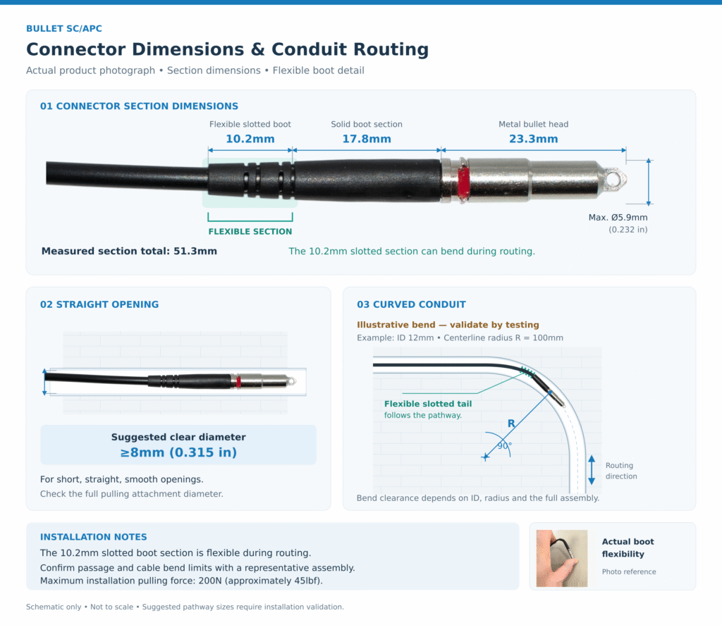
With the detachable SC housing uninstalled, the protected installation end has a maximum outside diameter of 5.9mm (0.232 in). It consists of a 23.3mm metal bullet head, a 17.8mm solid boot section and a 10.2mm flexible slotted boot section, giving a combined length of 51.3mm.
The slotted boot section can bend during routing, allowing the cable behind the connector to follow the pathway while the metal head remains straight.
Straight Openings
For short, straight and smooth openings, a clear diameter of at least 8mm (0.315 in) is suggested as an initial installation allowance. Include any pulling attachment, knot or protective wrapping when checking the maximum installation-end diameter.
Curved Conduits
Passage through a conduit bend depends on the actual internal diameter, centerline bend radius, bend geometry and complete installation assembly. The flexible boot assists routing, but sufficient clearance is still required for the metal head and solid boot section. Bend angle alone does not determine whether the assembly can pass.
The illustrated 90° bend, with a conduit internal diameter of 12mm and a centerline bend radius of 100mm, is a planning example rather than a verified minimum installation requirement.
Installation Checks
Check the pathway for obstructions, sharp edges and local restrictions. Verify passage using a representative assembly before installation, and observe the cable’s specified installation bend radius.
Keep pulling tension within 200N (approximately 45lbf). Pull smoothly, avoid shock loading and stop if the assembly becomes obstructed. Fit the SC housing after routing is complete.
Application
FTTH subscriber connections
Fiber routing through wall openings
Pre-terminated cable installation in suitable conduits
Building entry and premises fiber cabling
Connections between fiber access boxes and subscriber equipment
Installation projects requiring a detachable SC/APC housing
FAQ
What does “pullable and pushable” mean?
With the metal bullet head fitted and the SC housing uninstalled, the assembly can be pulled or pushed through suitable installation pathways.
What are the connector dimensions?
The maximum outside diameter is 5.9mm (0.232 in). The metal head measures 23.3mm, the solid boot 17.8mm and the flexible boot 10.2mm, giving a combined length of 51.3mm.
What size wall opening is suggested?
A clear diameter of at least 8mm (0.315 in) is suggested for short, straight, smooth openings. Include any pulling attachments when checking clearance.
Can it pass through a 90-degree conduit bend?
Suitability depends on the conduit’s internal diameter, bend radius and the complete assembly. Verify passage through the intended conduit before installation.
Is field splicing or polishing required?
No. The fiber is factory terminated. Simply remove the bullet head and assemble the SC housing after routing.
What is the maximum installation pulling force?
200N (approximately 45lbf). Avoid shock loading and stop pulling if the assembly becomes obstructed.
What armor material is used?
Stainless steel armor provides additional mechanical protection.
What lengths are available?
Lengths range from 5m to 200m in 5m increments.
