

Fiber-to-the-home (FTTH) networks are expanding rapidly across the United States as operators work to deliver faster broadband, improve service reliability, and prepare communities for long-term bandwidth growth. For many residential projects, a centralized split architecture offers a practical balance of network simplicity, deployment speed, and future flexibility.
In a typical centralized split design, optical signals travel from the central office through feeder and distribution networks before reaching an optical terminal near the subscriber. By concentrating the optical splitters in a fiber distribution hub (FDH), network operators gain a clear, manageable topology that is well suited to suburban developments, rural broadband projects, and new residential construction.
Rayoptic manufactures key outside-plant products used in this type of FTTH solution, including multiport service terminals (MSTs), OptiTap-compatible hardened SC/APC connectivity, pre-connectorized drop cables, and network interface devices (NIDs). These North America-ready products are designed for ISPs, WISPs, telecom operators, electric cooperatives, and fiber broadband providers.
What Is a Centralized Split FTTH Architecture?
A passive optical network (PON) allows one optical line terminal (OLT) port to serve multiple homes through passive optical splitters. In a centralized split architecture, the main splitter—commonly a 1×32 PLC splitter—is installed at one central outdoor location, usually inside an FDH.
The basic network path is:
Central office / headend → feeder cable → FDH and PLC splitter → distribution cable → MST/NAP → drop cable → NID → ONT
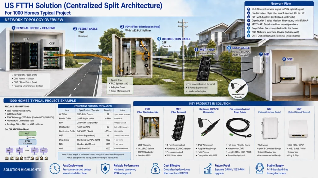
At the central office, the OLT converts service traffic into a PON optical signal. A high-fiber-count feeder cable carries the signal to the FDH. The FDH houses the splitter, adapter panels, splice trays, and fiber-management components. Distribution fibers then run from the FDH to MSTs or network access points positioned closer to groups of homes.
Each subscriber is connected through a pre-connectorized drop cable. The drop terminates at an outdoor NID, where the outside-plant connection is protected and organized before service continues to the indoor optical network terminal (ONT).
Why Use Centralized Splitting?
1. Straightforward network design
Placing splitters in a centralized FDH creates a clear point-to-multipoint structure. Technicians can identify feeder, splitter, distribution, and subscriber connections more easily, which supports efficient installation, troubleshooting, and documentation.
2. Easier testing and maintenance
Because the splitters and adapter interfaces are concentrated at an accessible hub, technicians can test fibers and isolate faults without visiting multiple splitter locations. This can simplify ongoing maintenance and reduce field-service time.
3. Flexible subscriber activation
Homes can be connected as service orders are received. Pre-connectorized terminals and drop cables allow operators to activate customers without extensive field splicing, making the architecture suitable for phased buildouts and variable take rates.
4. Faster outside-plant installation
Hardened plug-and-play interfaces reduce the number of specialized splicing operations required near the subscriber. Factory-terminated components can improve consistency and help crews complete installations more quickly.
5. Support for future upgrades
The passive outside plant can support multiple PON generations when the optical power budget and component specifications are properly designed. Operators can upgrade central-office electronics while continuing to use much of the installed fiber infrastructure.
Key Rayoptic Products for Centralized Split FTTH Networks
Reliable FTTH performance depends on every connection between the distribution network and the customer premises. Rayoptic focuses on the hardened connectivity products used in this critical final segment.
Rayoptic Multiport Service Terminal (MST)
The MST, also called a fiber terminal or network access point, provides a distribution interface for multiple subscriber drops. It is installed on a wall, pole, strand, pedestal, or other suitable outside-plant location near the homes it serves.
Rayoptic offers 2-, 4-, 6-, 8-, and 12-port MST configurations for different network densities. Available designs include terminals with pre-terminated multifiber feeder cable as well as stubless, tail-free MSTs with built-in PLC splitters. Rayoptic MST solutions can be configured with:
- 2-, 4-, 6-, 8-, and 12-port options
- Hardened SC/APC adapter interfaces
- Factory pre-connectorized construction
- Wall- or pole-mounting capability
- Locatable or dielectric feeder cable options
- Pre-terminated feeder lengths from 50 to 2,000 feet on applicable models
- Optional built-in PLC splitter designs
- Durable housings for outdoor deployment
By providing ready-to-connect subscriber ports, the MST helps operators add customers efficiently while keeping the distribution network organized.
Rayoptic Hardened SC/APC Connector
Outdoor FTTH connections must withstand water, dust, handling, and changing environmental conditions. Rayoptic hardened SC/APC connectivity provides a protected, OptiTap-compatible optical interface between the MST and subscriber drop cable.
Key features include:
- IP68 waterproof protection
- Plug and play design
- APC-polished optical interface
- Protective cap for unused or disconnected ports
- Compatibility with hardened MST interfaces
The hardened design reduces the need for field splicing at the terminal and helps protect optical performance at exposed connection points.
Rayoptic Pre-connectorized Drop Cable
The drop cable creates the final outside-plant link between the MST and the subscriber’s NID. Rayoptic pre-connectorized drop cables are supplied with factory-installed interfaces to support quick, repeatable field installation.
Rayoptic’s portfolio includes ruggedized SC/APC drop assemblies, hardened SC/APC-to-SC/APC toneable flat drops with pulling eyes, hardened-to-stub assemblies, and round-drop products with pulling grips. Available options can include:
- Flat drop, figure-8, and round cable constructions
- Hardened SC/APC connectivity
- Common lengths such as 50 ft, 100 ft, and 150 ft
- Black outdoor-rated cable jackets
- Optional toneable designs for route identification
- Pulling-eye or pulling-grip configurations for cable placement
- Dielectric and locatable constructions for different installation practices
Factory termination helps reduce installation variability and eliminates many on-site connectorization steps. Crews can route the cable, connect it to the MST, secure it along the approved pathway, and complete the customer-side termination.
Rayoptic Network Interface Device (NID)
The NID provides a protected transition point on the outside wall of the home. It organizes the incoming drop connection and provides space for optical adapters, splices, or connector storage before the fiber enters the premises.
Rayoptic supplies standard fiber NID enclosures as well as NID options with built-in reels for organized slack storage. Rayoptic NID solutions are designed for:
- Outdoor wall mounting
- Splice and connector storage
- Indoor/outdoor transition protection
- Pre-connectorized installation
- Neat, serviceable subscriber demarcation
A properly selected NID protects the fiber connection while giving technicians a consistent location for inspection and service.
A Typical Deployment Workflow
In a centralized split FTTH project, the feeder network is first built from the central office to the FDH. Splitter outputs are then assigned to distribution fibers running toward neighborhood MST locations. Once the MSTs are installed, subscriber drops can be added based on service demand.
For each home, a black pre-connectorized drop cable is connected to an available hardened MST port and routed to the NID. The NID protects the outside-to-inside transition, and an indoor fiber connection continues to the ONT. The ONT then provides the customer interface for broadband, voice, video, or other services supported by the operator.
Actual quantities, cable lengths, splitter ratios, and optical budgets must be determined through detailed engineering and field surveys. However, the modular nature of the architecture makes it adaptable to projects ranging from small subdivisions to large residential networks.
Choosing a Manufacturing Partner
FTTH components must work as a complete system. Connector geometry, sealing performance, cable structure, terminal port compatibility, and installation methods all affect field reliability. Working with a manufacturer that supplies the main drop-network components can simplify product selection and improve interoperability.
Rayoptic manufactures MSTs, hardened SC/APC connectivity, pre-connectorized drop cables, and NIDs for FTTH deployments. Its North America-ready portfolio includes multiple terminal port counts, locatable or dielectric feeder constructions, a broad range of cable lengths, toneable drop options, pulling-eye assemblies, built-in PLC splitter terminals, and NIDs with integrated reels. Product configurations can be selected according to port count, cable type, drop length, mounting method, and project requirements.
Build a Faster, More Reliable FTTH Drop Network
Centralized split architecture remains a strong option for US FTTH deployments that require a clear topology, efficient customer activation, and serviceable outside-plant infrastructure. When paired with pre-connectorized hardened components, it can reduce field work and support consistent installation across hundreds or thousands of homes.
Rayoptic provides the essential products that connect the distribution network to the subscriber: MST fiber terminals, IP68 hardened SC/APC connectors, pre-connectorized drop cables, and outdoor NIDs.
Contact Rayoptic to discuss product specifications, customized configurations, samples, or volume requirements for your next FTTH project. The Rayoptic team can provide a solution or proposal based on your network design and deployment requirements.


 English
 Spanish