
Fiber-to-the-home (FTTH) construction in the United States covers a wide range of service areas—from suburban communities to small towns, rural roads, and electric cooperative territories. Because density, distance, pole capacity, conduit space, labor cost, and subscriber take rate vary significantly, there is no single splitter architecture that fits every project.
For networks that need to reduce distribution fiber count and place optical splitting closer to subscribers, a distributed split architecture can offer an efficient and scalable approach. Instead of concentrating all splitters in one fiber distribution hub (FDH), distributed designs place splitters in closures, pedestals, or fiber terminals throughout the outside plant.
Rayoptic supports these networks with North America-ready FTTH products, including MST fiber terminals with built-in PLC splitters, IP68 hardened SC/APC connectivity, pre-connectorized drop cables, y outdoor fiber NIDs.
In a passive optical network (PON), an optical line terminal (OLT) port serves multiple optical network terminals (ONTs) through passive optical splitters. The location and arrangement of those splitters determine the network architecture.
The Fiber Broadband Association describes a distributed split as a design in which subscriber addresses are assigned through the built outside plant rather than changed through cross-connect jumpers at a centralized splitter cabinet. Splitters are commonly installed individually in closures, pedestals, or terminals closer to subscribers.
A representative distributed FTTH path is:
Central office / OLT → feeder cable → first-stage splitter → distribution cable → local splitter MST → pre-connectorized drop cable → NID → ONT
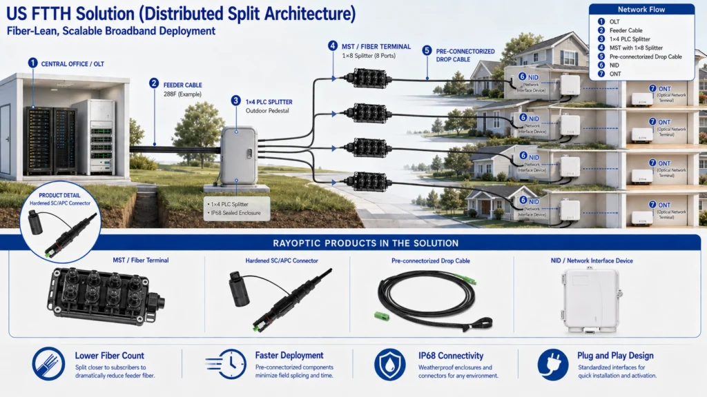
For example, a provider may use a 1×4 first-stage splitter feeding four local 1×8 splitter terminals. The combined split ratio is 1×32, but splitting is performed in two geographic stages rather than at one FDH.
The exact split combination must be selected according to the PON class, optical loss budget, route length, connector loss, splice loss, engineering margin, and the operator’s capacity strategy.
In a traditional distributed design, individual splitters are placed at selected outside-plant locations. A splitter may be installed in a splice closure or pedestal and feed nearby terminals or subscriber drops. Because the split point is closer to the served area, the network can use lower-fiber-count distribution cables than a centralized FDH design.
This approach can be suitable where neighborhoods are separated into clear serving areas and where the operator wants to avoid a large centralized cabinet.
A cascaded design uses two or more splitter stages to reach the final ratio. Common examples include:
The first splitter divides the PON signal among several routes. A second splitter—often integrated into a local MST—then serves homes near the terminal. This reduces the number of fibers required along long distribution routes and allows smaller cables to serve dispersed subscriber clusters.
An optical tap network uses splitters with unequal power outputs along a route. Part of the optical power serves subscribers at one location, while the remaining power continues downstream to additional tap terminals.
This approach can be highly fiber-efficient for linear routes and low-density areas, but it requires careful optical engineering. Tap values, distance, connector loss, and downstream subscriber count must be planned so that every ONT remains within its permitted receive-power range.
Centralized splitting typically requires a dedicated distribution fiber from the FDH toward each subscriber position. Distributed splitting allows one feeder or distribution fiber to reach a local splitter that serves multiple homes, reducing fiber count along the route.
Lower-fiber-count cables can reduce cable diameter, weight, and space requirements. This can be valuable where existing conduits have limited capacity or where aerial pole loading and cable congestion are important considerations.
Distributed designs use closures, pedestals, and terminals placed throughout the network. Eliminating or reducing large FDH cabinets can simplify deployments where cabinet real estate, permitting, aesthetics, or pad construction is difficult.
Rural and lower-density service areas often contain small groups of homes separated by long distances. Placing splitter terminals near each group can reduce the amount of high-count fiber that must be installed across the entire route.
Distributed networks can use factory-terminated MST ports and drop cables. Once the terminal is installed, a technician can connect a hardened drop cable, route it to the subscriber NID, and complete the final connection without connectorizing the MST interface in the field.
Both architectures are widely used tools. The best choice depends on project conditions.
| Design consideration | Distributed split | Centralized split |
|---|---|---|
| Splitter location | Closures, pedestals, or terminals throughout the network | Central FDH or similar cabinet |
| Distribution fiber count | Generally lower | Generally higher |
| Cabinet requirement | Smaller distributed enclosures | Larger centralized cabinet often required |
| Subscriber reassignment | Usually fixed after construction | More flexible through FDH jumpers |
| Testing and troubleshooting | Requires accurate records of multiple split points | Centralized access can simplify isolation |
| Typical strength | Fiber-efficient coverage of variable or low-density areas | Flexibility and centralized management in concentrated service areas |
Many operators mix architectures across one network. A suburban zone may use centralized splitting, while a rural extension uses cascaded splitters or optical taps. Split architecture should therefore be treated as an engineering tool rather than a universal rule.
The success of a distributed network depends heavily on the products installed at local split points and subscriber connections. Rayoptic manufactures the main outside-plant components required from the distributed terminal to the home.
An MST with an integrated PLC splitter combines the local split point and hardened subscriber ports in one compact enclosure. This configuration is especially useful in cascaded distributed networks because a distribution fiber can feed the terminal directly and the terminal can provide multiple ready-to-connect drop ports.
Rayoptic’s FTTH portfolio includes:
MST selection should match the planned splitter ratio, homes passed, expected take rate, reserve-port strategy, mounting environment, and approved connector interface.
Distributed split terminals are installed outdoors, so subscriber interfaces require dependable environmental protection. Rayoptic hardened SC/APC assemblies provide protected connectivity between the MST and the pre-connectorized drop cable.
Key features include:
Factory-terminated hardened interfaces help reduce field connectorization and support repeatable subscriber activation.
The drop cable connects the local MST to the subscriber NID. Rayoptic provides pre-connectorized drop assemblies for different US FTTH installation practices, including:
Black outdoor-rated cable jackets are commonly used between the MST and NID, while the green color is limited to SC/APC connector components.
The NID provides a protected demarcation point on the outside wall of the subscriber premises. It supports cable routing, connector or splice protection, slack storage, and the transition from outside plant to the indoor ONT connection.
Rayoptic offers standard fiber NIDs as well as an NID with a built-in reel. The reel-type version can be supplied with factory-terminated SC/APC drop cable pre-wound inside the enclosure, helping installers manage cable neatly and reduce field splicing. Available cable options include armored or non-armored construction and lengths up to 150 ft on applicable configurations.
Consider a project designed around an overall 1×32 split:
This design can serve up to 32 subscriber locations per OLT port while keeping distribution cable counts relatively low. Actual serving capacity and optical performance must be confirmed through detailed engineering.
Distributed splitting provides significant fiber-efficiency benefits, but it also requires disciplined planning:
Because splitters are distributed throughout the network, accurate records and labeling become especially important for troubleshooting and future maintenance.
Distributed split architecture is a practical option for US FTTH projects that need lower fiber counts, smaller outside-plant cables, and flexible coverage of dispersed subscriber groups. Traditional distributed splitters, cascaded splitter combinations, and optical tap designs each provide different cost and deployment advantages.
Rayoptic supplies the connectivity products required for the final network segment: MST fiber terminals with built-in PLC splitters, IP68 hardened SC/APC connectors, pre-connectorized drop cables, and outdoor fiber NIDs.
Contact Rayoptic to discuss your splitter plan, MST port count, drop cable construction, cable length, mounting method, connector interface, NID configuration, samples, or volume requirements.


 3F, Edificio E, Parque Científico Dahong,
Comunidad de Baihua, distrito de Guangming,
Shenzhen, Guangdong 518107, China
 English English
 Spanish
